Start Battery
Moderator: KenKrawford
-
Joel Indulgence
- Posts: 11
- Joined: Fri Nov 04, 2005 1:39 am
Start Battery
I am in the process of adding a dedicated start battery, any and all info regarding installation materials wiring routes etc would be helpful.I would like to do it myself so keep it simple, we have the third water tank in the port dinette. Pictures would be great if possible. thanks in advance. Joel Indulgence Hull#256 
Last edited by Joel Indulgence on Sat Nov 12, 2005 3:51 am, edited 1 time in total.
Start Battery with Water Tank
We are also planning a starting battery project and have the third water tank. We are looking into the OPTIMA brand, since the batteries are quite small in size. They are quite hearty and can be placed in any orientation (even upside down). Hopefully we can share info on doing the starting battery with the third tank.
Barbara
#76 Freedom
"Wherever we want to go, we go. That’s what a ship is, you know. It’s not just a keel and hull and a deck and sails. That’s what a ship needs. But what a ship is… what the Black Pearl really is… is freedom."
#76 Freedom
"Wherever we want to go, we go. That’s what a ship is, you know. It’s not just a keel and hull and a deck and sails. That’s what a ship needs. But what a ship is… what the Black Pearl really is… is freedom."
-
LONGHAWK
starting battery
I added a starting battery. I do not have the third water tank, so the third battery was added to the port storage area (where I believe your water tank is). I have heard of folks adding the third one to the stbd storage area forward of the sink. I will search old emails and see if I can find their info.
I added the Balmar Duo Charge to handle the charging duties. Originally, the dealer had installed an isolator, but I removed it as it causes a 0.7 volt drop across the isolating diode, resulting in a significantly diminished charging capability. I have the engine battery switch totally isoltade to this starting battery. The two house batteries are swiched by the 1/2/both switch. There is no way that the starting battery can be discharged by any house load.
I can send a wiring schematic if you like.
Sam
LONGHAWK #173
Start Battery
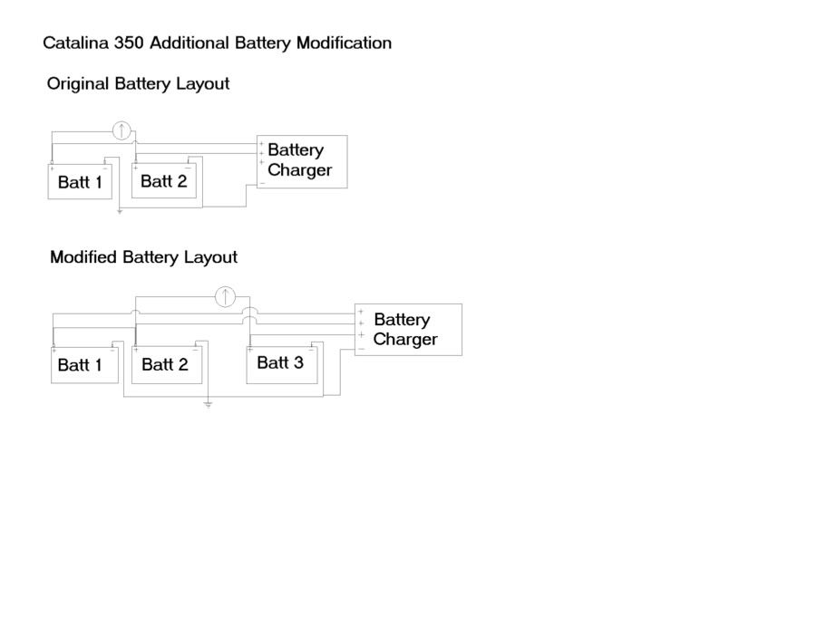
I too added the third battery, with no third water tank. All I had to purchase was a 48" cable, and a 14" cable, in addition to the battery and box. I have both 4D's on battery switch 1, and the Start battery on switch two. I also ran an additional wire from the third spot on the Charles charger to the new battery. So the start battery gets a charge when the battery charger is on. I left the original two charger wires as they were on the 4D's.
If I recall, we pulled a long red cable off one of the 4D's, the one from the batt switch 2, and when we pulled it back out from behind, it reached the started battery. We used the 48" black cable to run from the start to the negative terminal on one of the 4D's, then used the 14" red cable to jump between the post of the 4D's.
I had my physicist friend help me, so I'm really telling you what I watch him do .... that's the "we' part.
-
Joel Indulgence
- Posts: 11
- Joined: Fri Nov 04, 2005 1:39 am
Start battery
If you could send me those wiring diagrams, or post them that would be great, thanks Sam.
-
jnnielsen
- Site Admin
- Posts: 37
- Joined: Sun Oct 30, 2005 7:04 pm
- Location: Wind * Rose - Marina del Rey, CA
- Contact:
Wiring diagram would be appreciated.
Triumph,
Would love to get a wiring diagram or photos of how you did your dedicated starter battery. Sounds like just what I want to do on Wind*Rose. I just don't have any physicists to help me.
Jerry Nielsen - Webmaster C350IA
Would love to get a wiring diagram or photos of how you did your dedicated starter battery. Sounds like just what I want to do on Wind*Rose. I just don't have any physicists to help me.
Jerry Nielsen - Webmaster C350IA
wire diagram
Triumph here. Got your message, I have to figure out how to post it, stand by. I also want to post pics of the props, and need to figure that out too.
Wiring Diagram
Jerry, here is the diagram you asked for. I was thinking pics might be more helpful though.
-
jnnielsen
- Site Admin
- Posts: 37
- Joined: Sun Oct 30, 2005 7:04 pm
- Location: Wind * Rose - Marina del Rey, CA
- Contact:
Many thanks
Triumph,
Many thanks. The diagram will be a great help.
Jerry Nielsen
Many thanks. The diagram will be a great help.
Jerry Nielsen
-
Steve Wark
- Posts: 1
- Joined: Sat Jan 07, 2006 5:18 pm
Combiner/isolater approach.
They way mine was done (by the dealer) is a little more convenient. In addition to the Off-1-Both-2 switch, there is an Engine On-Off switch on the 350. The Off -1-Both-2 switch has it's common out connected to the engine On-Off in the standard configuration.
For my starting battery, first the wire connecting the two switches was removed. A seperate Group 27 was mounted under the port settee and connected to the engine On-Off switch. A combiner was used to connect the house bank to the starting battery.
The combiner is normally isolating the two banks, with only the starting battery connected to the engine starting circuit, so starting the eninge only uses that battery regardless of the Off-1-Both-2 switch position (can't be off, though). With the engine running and charging at >13.3 AMPS the combiner kicks in and the house bank and the starting battery are both being charged. When the enigne is stopped, the voltage drops below 13.3, the combiner kicks out and the starting battery is isolated from the house bank.
The downside to my configuration is that the combiner doesn't have an override to allow me to gang all the batteries together to start the enigne. More expensive ones do. It's only likely to be a problem if the battery goes bad, and I carry the original wiring so that I can reconfigure if that happens.
I've been meaning to diagram the installation, but I don't know off the top of my head exactly where the connections are. And with the boat 2 hours away, it's likely to be summer before I get to it.
"Wandering Skye"
C-350 #85
C-350 #85